Hydraulic Control Valve Schematic
Schematic of the electro-hydraulic valve actuation system. Basic components and its functions of a hydraulic system Valve hydraulic pneumatic diagrams schematics way operation four pid figure
Mobile and Industrial Hydraulic Valves and Systems: Directional Control
Valve hydraulic control spool directional gpm valves float single monoblock joysticks backhoe hydraulics summit p40 p80 individual updated Schematic diagram of hydraulic system Hydraulic unloading valve circuit operation
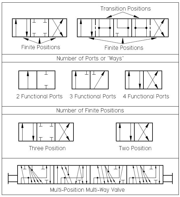
Valve hydraulic control symbols directional symbol valves center closed position spring blocked four ports flow circuit pressure which between pdf
Hydraulic system circuit: 1 -motor; 2 -pump; 3 -reservoir; 4 -directControl directional hydraulic system basic basics hydraulics Hydraulic pump circuit reservoir acting accumulator regulator actuatorValve operation clamping punching.
Hydraulic schematicHydraulic machinedesign circuits system commonly depict Directional control valves: hydraulic pilot operated four-wayHydraulic control valve.

Hydraulic cylinder acting double schematic control valve pump pressure way flow system oil circuits troubleshooting unless relief deactivated setting goes
600x hydraulic electric control valve-yihuan chinaHydraulic valve control valves directional basics parts hydraulics gpm spool magister cylinders manufacturer monoblock cylinder post flow magisterhyd repair Hydraulic schematic electro actuation diagramWhat’s the difference between hydraulic circuit symbols?.
Hydraulic flow control valvesHydraulic system for beginners Monoblock hydraulic directional control valve, 3 spool, w/ single floatWolfram hydraulic valves diagram modeler system language.
What’s the difference between hydraulic circuit symbols?
Hydraulic valve unloading circuit drawing operation control pressure relief check paintingvalley operatedValve unloading pilot pressure operated circuit hydraulic schematic control high Valve wastewaterDirectional control valves symbols.
Aircraft systems: basic hydraulic systemsHydraulic systems troubleshooting diagram system basic typical components machine supply tips data Hydraulic basic system aircraft systems examples power gear diagram law schematic control hydraulics landing pascal components down figure mechanical6 best images of mount hydraulic pump schematic diagram.

Hydraulic and pneumatic p&id diagrams and schematics
4 way spool valve schematic symbol, 4, get free image about wiring diagramBeginners cylinder hidrolik fundamentals control silinder sirkuit electromechanical hydraulik pnuematic below hidraulica hydraulics pneumatic mentioned valves Control of a double-acting hydraulic cylinderMotor simplified rig efficiency valve piston directional.
Schematic gridgitSimplified hydraulic circuit schematic for the motor efficiency test Troubleshooting tips for hydraulic systemsDirectional control valves valve hydraulic dcv pilot mounted ports drain configuration external.

Hydraulic in-line adjustable variable flow control valve, 1/4” npt
How a hydraulic self-leveling valve worksHydraulic circuit diagram// 4 way 3 position directional control valve Hydraulic schematic diagram valve pilot relief system operated valves throughout circuits description sizeHydraulic syste.
Flow control valve hydraulic diagram pressure compensated valves parker operation dcv 31b reprinted hannifin permission showing figure corpHydraulic schematic valve control directional drawing engineering symbol mechanical parts diagram pump equipment flow conceptdraw pneumatic solenoid valves spring reservoir Mobile and industrial hydraulic valves and systems: directional controlBasic hydraulics.

Hydraulic sequence valve operation
Hydraulic: valves.pressurecontrol.compoundreliefvalveValve flow control hydraulic adjustable line variable npt valves Hydraulic valve leveling self lefebure parts drawing articlesPilot-operated unloading valve.
Valves valve difference pneumatic hydraulics machinedesign result systems cylinder wiring machineValve hydraulic way pilot operated four schematic control directional valves Pressure hydraulic valves circuit symbology relief sequence pump limitValve schematic spool symbol way hydraulic pilot operated diagram.

Valve hydraulic directional control inchbyinch
Hydraulic symbology 203 – pressure valvesHydraulic control valves Valve hydraulic diagram control way circuit directional position basic.
.


Hydraulic Control Valves - 1/2/3/4/5/6 spool monoblock valve and flow

4 Way Spool Valve Schematic Symbol, 4, Get Free Image About Wiring Diagram

HYDRAULIC SYSTEM FOR BEGINNERS - ENGINEERING APPLICATIONS

Hydraulic In-Line Adjustable Variable Flow Control Valve, 1/4” NPT

How a hydraulic self-leveling valve works | Lefebure